
Cooling towers theory
Cooling towers can be used to remove heat from various sources such as machinery or heated process material. The primary use of large, industrial cooling towers is to remove the heat absorbed in the circulating cooling water systems used in power plants, petroleum refineries, petrochemical plants, natural gas processing plants, food processing plants, semi-conductor plants, and for other industrial facilities such as in condensers of distillation columns, for cooling liquid in crystallization, etc. The circulation rate of cooling water in a typical 700 MW coal-fired power plant with a cooling tower amounts to about 71,600 cubic metres an hour (315,000 U.S. gallons per minute) and the circulating water requires a supply water make-up rate of perhaps 5 percent (i.e., 3,600 cubic metres an hour). If that same plant had no cooling tower and used once-through cooling water, it would require about 100,000 cubic metres an hour and that amount of water would have to be continuously returned to the ocean, lake or river from which it was obtained and continuously re-supplied to the plant. Furthermore, discharging large amounts of hot water may raise the temperature of the receiving river or lake to an unacceptable level for the local ecosystem.
Elevated water temperatures can kill fish and other aquatic organisms. (See thermal pollution.) A cooling tower serves to dissipate the heat into the atmosphere instead and wind and air diffusion spreads the heat over a much larger area than hot water can distribute heat in a body of water. Some coal-fired and nuclear power plants located in coastal areas do make use of once-through ocean water. But even there, the offshore discharge water outlet requires very careful design to avoid environmental problems. Petroleum refineries also have very large cooling tower systems. A typical large refinery processing 40,000 metric tonnes of crude oil per day (300,000 barrels per day) circulates about 80,000 cubic metres of water per hour through its cooling tower system. The world’s tallest cooling tower is the 200 metre tall cooling tower of Niederaussem Power Station.
With respect to drawing air through the tower, there are three types of cooling towers :
- Natural draft: which utilizes buoyancy via a tall chimney. Warm, moist air naturally rises due to the density differential to the dry, cooler outside air. Warm moist air is less dense than drier air at the same pressure. This moist air buoyancy produces a current of air through the tower.
- Mechanical draft: which uses power driven fan motors to force or draw air through the tower.
- Induced draft: A mechanical draft tower with a fan at the discharge which pulls air through tower. The fan induces hot moist air out the discharge. This produces low entering and high exiting air velocities, reducing the possibility of recirculation in which discharged air flows back into the air intake. This fan/fin arrangement is also known as draw through.
- Forced draft: A mechanical draft tower with a blower type fan at the intake. The fan forces air into the tower, creating high entering and low exiting air velocities. The low exiting velocity is much more susceptible to recirculation. With the fan on the air intake, the fan is more susceptible to complications due to freezing conditions. Another disadvantage is that a forced draft design typically requires more motor horsepower than an equivalent induced draft design. The forced draft benefit is its ability to work with high static pressure. They can be installed in more confined spaces and even in some indoor situations. This fan/fill geometry is also known as blow-through.
- Fan assisted natural draft: A hybrid type that appears like a natural draft though airflow • is assisted by a fan. Hyperboloid (a.k.a. hyperbolic) cooling towers (Image 1) have become the design standard for all natural-draft cooling towers because of their structural strength and minimum usage of material. The hyperboloid shape also aids in accelerating the upward convective air flow, improving cooling efficiency. They are popularly associated with nuclear power plants. However, this association is misleading, as the same kind of cooling towers are often used at large coal-fired power plants as well. Similarly, not all nuclear power plants have cooling towers, instead cooling their heat exchangers with lake, river or ocean water.
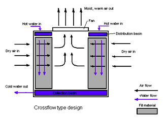
Cross Flow
Counter Flow
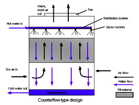
Common to both designs
The interaction of the air and water flow allow a partial equalization and • evaporation of water.
- The air, now saturated with water vapour, is discharged from the cooling tower.
- A collection or cold water basin is used to contain the water after its interaction with the air flow.
Some commonly used terms in the cooling tower industry
- Drift – Water droplets that are carried out of the cooling tower with the exhaust air. Drift droplets have the same Concentration of impurities as the water entering the tower. The drift rate is typically reduced by employing baffle-like devices, called drift eliminators, through which the air must travel after leaving the fill and spray zones of the tower.
- Blow-out – Water droplets blown out of the cooling tower by wind, generally at the air inlet openings. Water may also be lost, in the absence of wind, through splashing or misting. Devices such as wind screens, louvers, splash deflectors and water diverters are used to limit these losses.
- Plume – The stream of saturated exhaust air leaving the cooling tower. The plume is visible when water vapour it contains condenses in contact with cooler ambient air, like the saturated air in one’s breath fogs on a cool day. Under certain conditions, a cooling tower plume may present fogging or icing hazards to its surroundings. Note that the water evaporated in the cooling process is “pure” water, in contrast to the very small percentage of drift droplets or water blown out of the air inlets.
- Blow-down – The portion of the circulating water flow that is removed in order to maintain the amount of dissolved solids and other impurities at an acceptable level. It may be noted that higher TDS (total dissolved solids) concentration in solution results in greater potential cooling tower efficiency. However the higher the TDS concentration, the greater the risk of scale, biological growth and corrosion.
- Leaching – The loss of wood preservative chemicals by the washing action of the water flowing through a wood structure cooling tower.
- Noise – Sound energy emitted by a cooling tower and heard (recorded) at a given distance and direction. The sound is generated by the impact of falling water, by the movement of air by fans, the fan blades moving in the structure, and the motors, gearboxes or drive belts.
- Approach – The approach is the difference in temperature between the cold-water temperature and the entering-air wet bulb temperature (twb). Since the cooling towers are based on the principles of evaporative cooling, the maximum cooling tower efficiency depends on the wet bulb temperature of the air. The wet-bulb temperature is a type of temperature measurement that reflects the physical properties of a system with a mixture of a gas and a vapour, usually air and water vapour
- Range – The range is the temperature difference between the water inlet and water exit.
- Fill – Inside the tower, fills are added to increase contact surface as well as contact time between air and water. Thus they provide better heat transfer. The efficiency of the tower also depends on them. There are two types of fills that may be used:
- Film type fill (causes water to spread into a thin film)
- Splash type fill (breaks up water and interrupts its vertical progress)
QUICK LINKS
REGISTERED OFFICE
H.no 1-5-120, New maruti Nagar,
Kothapet, Saroor Nagar P.O.,
Hyderabad – 500060
Telangana State, India.
Mobile : +91-9440891921
Tel : +91-40-2405 1905
FACTORY
#Plot No:. 8/2, Survey No 519,
TSIIC IP Nadargul Village
Saroor Nagar, Hyderabad – 500036,
Telangana, India.
Email : sales@sitscoolingtowers.com / venkatceo@sitscoolingtowers.com